
Multifunction time relays are particularly accurate in reaching the time limit even over long periods of time. With the universal supply of 12…240V AC/DC and different functions it is possible to find solutions even to the most challenging problems.
The brain chip of your application-specific miniature controller is the ideal solution for realizing custom control applications within minimum space at low-cost.
Time functions available in the MTR17-A07-U240-116 relay:
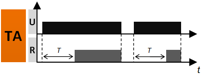 |
ON delay (TA) – on applying the supply voltage U the set interval T begins – off-delay of the output relay R. After the interval T has lapsed, the output relay R switches on and remains on until supply voltage U is interrupted. |
 |
ON for the set interval (TB) – on applying the supply voltage U immediately switches the output relay R on for the set interval T. After the interval T has lapsed, the output relay R switches off. |
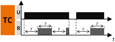 |
Symmetrical cyclical operation pause first (TC) – applying the supply voltage U starts the cyclical operation from the T interval – switching the output relay R off followed by switching on the output relay R for the interval T. The cyclical operation lasts until the supply voltage U is interrupted. |
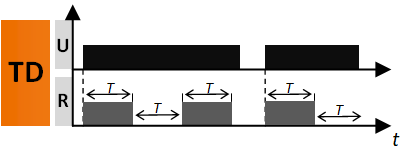 |
Symmetrical cyclical operation pulse first (TD) – applying the supply voltage U starts the cyclical operation from switching on the output relay R for the set interval T. After the interval T has lapsed, the output relay R switches off for the interval T. The cyclical operation lasts until the supply voltage U is interrupted. |
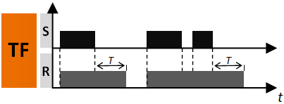 |
OFF delay with the control contact S (TF) – the input of the time relay is supplied with voltage U continuously. Closing of the control contact S immediately switches on the output relay R. Opening of the control contact S starts the set time of the delayed switching off of the output relay R. After the interval T has lapsed, the output relay R switches off. If the control contact S is closed during the interval T, the already measured time is reset, and the output relay R is switched on again. The OFF delay of the output relay R will start when the control contact S is opened again. |
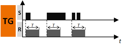 |
Single shot for the set interval triggered by closing of the control contact (TG) – single shot for the set interval triggered by closing of the control contact (TG) – The input of the time relay is supplied with voltage U continuously. Closing of the control contact S immediately switches the output relay R on for the set interval T. After the interval T has lapsed, the output relay R is switched off. In the course of the interval T, any opening of the control contact S does not affect the function to be performed. The output relay R may be switched on again for the set interval, after the interval T has lapsed, by closing the control contact S again. |
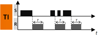 |
ON for the set interval triggered with the control contact S (TI) -the input of the time relay is supplied with voltage U continuously. Closing of the control contact S does not start the interval T, and it does not change the position of the output relay R. Opening of the control contact S immediately switches on the output relay R for the set time. After the interval T has lapsed, the output relay R switches off. Opening and closing of the control contact S in the course of the interval T does not affect the function to be performed. The output relay R may be switched on again for the set interval with another closing and opening of the control contact S. |
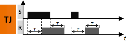 |
ON and OFF delay with the control contact (TJ) – – The input of the time relay is supplied with voltage U continuously. Closing of the control contact S starts the interval T – on-delay of the output relay R. After the interval T has lapsed, the output relay R switches on. Opening of the control contact S begins further measurement of the interval T – off-delay of the output relay R, and after the interval has lapsed, the output relay switches off. In case the time for which the control contact S is closed in the course of measurement of the on-delay of the output relay R is shorter than the set interval T, the output relay R will switch on after the set interval T, and the output relay R will remain in on position for the interval T. When the output relay R is in on position, closing of the control contact S does not affect the function to be performed. |
Connections |
Front Panel |
 |
 |
| Version | MTR17-A07-U240-116 |
|---|---|
| Output Circuit |
|
| Contact arrangement | 1NO/NC |
| Rated switching current In | AC1 – 16A/250V AC DC1 – 16A/24V DC |
| Maximum continuous current | 12A |
| Switching load range AC1 | 4 000VA |
| Rated/maximum contact voltage | 250/400V AC |
| Contact resistance | ≤ 100mΩ |
| Maximum switching frequency |
600 cycles/h |
| Input Circuit |
|
| Supply voltage Un | 12…240V AC/DC |
| Supply voltage range |
0,8…1,1Un (9,6…264V) |
| Rated consumption | AC: ≤ 2,5VA DC: ≤ 2W |
| Rated frequency | 47…63Hz |
| Minimum trigger level S-A2 (sensitivity) | 0,7Un |
| Minimum control S pulse length | AC: ≥ 90ms DC: ≥ 45ms |
| S loadable | yes |
| Rated surge voltage | 1 000V |
| Insulation |
|
| Insulation rated voltage | 250V AC |
| Rated surge voltage | 4 000V (1,2/50μs) |
| Overvoltage category | III |
| Pollution degree |
2 |
| Flammability | PCB: V0, housing: HB |
| Dielectric strength input-output | 4 000V AC |
| Dielectric strength open contact | 1 000V AC |
| Dielectric strength between contacts | – |
| General Data |
|
| Electrical life AC1 at 50% In | ≥ 150 000 |
| Mechanical life | ≥ 30 000 000 |
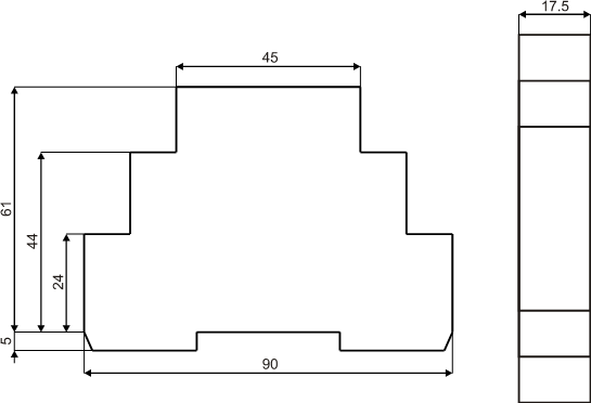
| Dimensions (L x W x H) | 90 x 17,5 x 66mm |
| Weight | 53g |
| Ambient temperature | -20°C …. +55°C |
| Relative humidity | 85% |
| IP rating | IP20 |
| Shock resistance | 15g |
| Vibration resistance | 0,35mm (10…55Hz) |
| Terminals | max 2,5 mm² |
| Installation | DIN rail 35mm |
| Time Module |
|
| Functions |
TA, TB, TC, TD, TF, TG, TI, TJ |
| Time ranges |
1s, 10s, 1m, 10m, 1h, 10h, 100h |
| Timing adjustment | smooth 0,1…1,0 x range |
| Setting accuracy |
5% |
| Repeatability | 0,5% |
| Recovery time | ≤ 100ms |
Order in e-shop |
Order on allegro |
Order by e-mail |
 |
 |
| MTR17-A07-U240-XXX Datasheet | |
| Time Relay selection table | |
| Declaration of conformity CE |
Join as. Dobry Czas sp. z o.o. invites to cooperation sales partners. Submit your proposal marketing@dobry-czas.pl

It is used to secure loads (eg. motors) from the voltage unbalance, incorrect phase sequence or damage to the executive contactor’s contacts.
read more
Welcome to our online store. The full portfolio of products. The certainty of the transaction.
read more

